
Milling cutters are generally multi-tooth tools. Due to the participation of multiple teeth in cutting simultaneously, with long cutting edges, and the ability to adopt higher cutting speeds, the productivity is high. Different milling cutters can be used to process flat surfaces, grooves, steps, etc., as well as gear teeth, threads, spline shafts, and various forming surfaces.
Structure of Milling Cutters
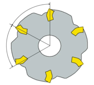
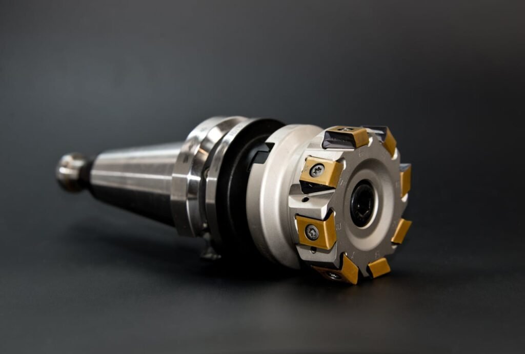
Ⅰ.Taking indexable milling cutters as an example:
1)Main Geometric Angles
Milling cutters have a main rake angle and two clearance angles, one called the axial clearance angle and the other called the radial clearance angle.
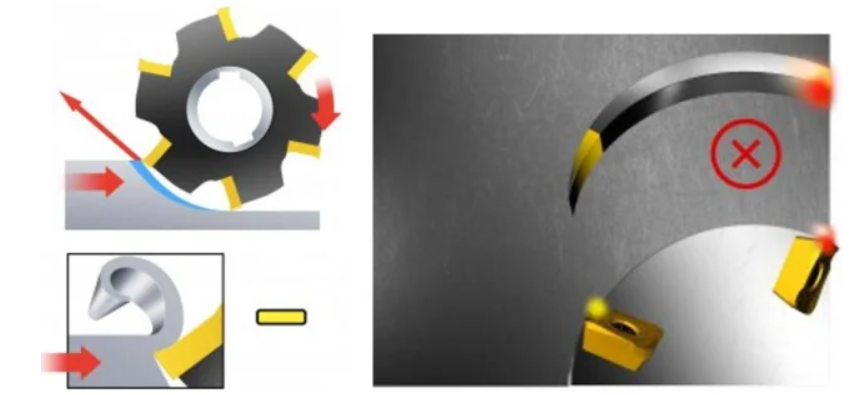
The radial clearance angle γf mainly affects the cutting power; the axial clearance angle γp affects the formation of chips and the direction of axial forces, with positive values of γp causing the chips to fly away from the workpiece surface.
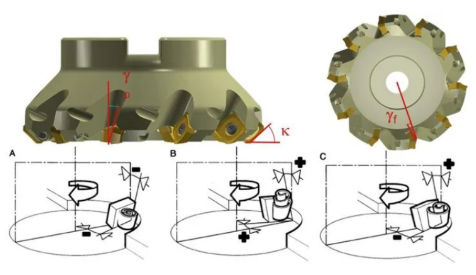
Lead angle (front face contact surface)
Negative lead angle: Used for steel, steel alloys, stainless steel, and cast iron.
Positive lead angle: Used for sticky materials and some high-temperature alloys.
Neutral lead angle: Used for threading, grooving, contour turning, and form cutting.
2)Geometry of Milling Cutter
Firstly:Geometry of Milling Cutter
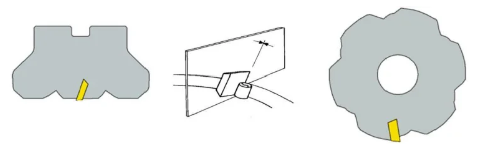
Cutting is light and fast, chip removal is smooth, but cutting edge strength is relatively poor. Suitable for processing soft materials, stainless steel, heat-resistant steel, ordinary steel, and cast iron, etc. This form should be preferred in small power machine tools, insufficient rigidity of process systems, and when chip lumps are generated.
Advantages:
Smooth cutting, smooth chip removal, good surface roughness.
Disadvantages:
Affects cutting edge strength. Not conducive to cutting contact. The workpiece may come off the machine table.
Secondly:Both edges adopt negative angles.
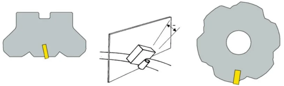
Strong impact resistance, using negative inserts, suitable for rough milling of cast steel, cast iron, and high hardness, high strength steel.
However, milling power consumption is high, requiring excellent rigidity of the process system.
Advantages:
Beneficial for cutting edge strength, increasing productivity, can push the workpiece towards the machine table.
Disadvantages:
Greater cutting force may lead to chip blockage.
Finally: One edge is at a positive angle and the other edge is at a negative angle.
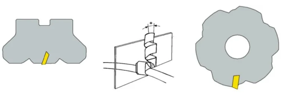
Cutting edge has strong impact resistance and is also sharp. Suitable for machining steel, cast steel, and cast iron. It also performs well during heavy-duty milling.
Advantages:
Smooth chip removal, favorable cutting force, wide application range.
3)Milling cutter pitch
1)Dense teeth: High feed rate, high milling force, small chip space.
2)Standard teeth: Normal feed rate, milling force, and chip space.
3)Sparse teeth: Low feed rate, small milling force, large chip space.
If the milling cutter is not equipped with a dedicated finishing insert, the surface roughness depends on whether the feed per revolution exceeds the width of the insert’s finishing plane.
Example: Slot milling & contour milling
Teeth Number:
- Sparse or standard teeth are used for slot milling (safety).
- Dense teeth are used for contour milling (productivity).
Ⅱ.Types and Applications of Milling Cutters:
Milling cutters can be classified into end mills and slab mills based on the tooth structure.
According to the relative position of the teeth and the axis of the milling cutter, they can be divided into cylindrical milling cutters, angular milling cutters, face milling cutters, and form milling cutters.
Based on the shape of the teeth, they can be classified into straight-tooth milling cutters, spiral-tooth milling cutters, helical-tooth milling cutters, and curved-tooth milling cutters.
According to the structure of the tool, they can be divided into integral milling cutters, combination milling cutters, sets or kits of milling cutters, insert milling cutters, machine-clamped welding milling cutters, and indexable milling cutters.
However, they are usually classified based on the machining form of the back of the cutting teeth.
Mills can be divided into the following categories:
(1) Face Milling Cutters: including integral face milling cutters, insert face milling cutters, and machine-clamped indexable face milling cutters, used for rough, semi-finish, and finish machining of various flat surfaces, step surfaces, etc.
(2) End Mills: used for milling step surfaces, side surfaces, grooves, recesses, holes of various shapes on workpieces, and internal and external curved surfaces. End mills can be broadly categorized into left-hand and right-hand rotation types. Many people still have no concept of left-hand and right-hand rotation.
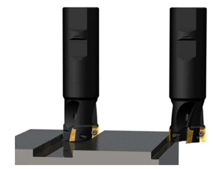
Right-hand Rotation End Mill:
Firstly, whether a tool is left-hand or right-hand rotation can be determined as follows:
facing a vertical milling cutter, if the flute rises from the lower left to the upper right, it is right-hand rotation; if the flute rises from the lower right to the upper left, it is left-hand rotation.
Right-hand rotation can also be determined using the right-hand rule:
the curved fingers represent the rotation direction, and the raised thumb represents the upward direction, indicating right-hand rotation. The helical flute serves the purpose of chip evacuation and also constitutes the front angle and the front portion of the milling cutter.
Left-handed Milling Cutter:
Left-handed milling cutters are typically chosen for high-precision machining needs. They are commonly used in the precision machining of mobile phone buttons, membrane switch panels, LCD panels, acrylic lenses, and other precision components. For high-demand applications, especially in the production and machining of mobile phone buttons or electrical panels, where high precision and smoothness are required, down-cutting left-hand rotation milling cutters are selected to avoid white edges on the cutting edge and burrs on the machined parts.
(3) Keyway Milling Cutter: Used for milling keyways and the like.
(4) Slot Milling Cutter and Saw Blade Milling Cutter: Used for milling various slots, sides, step faces, and sawing, etc.
(5) Special Slot Milling Cutter: Used for milling various special slot shapes, including shaped slot milling cutters, half-moon keyway milling cutters, dovetail slot milling cutters, etc.
(6) Angle Milling Cutter: Used for milling straight grooves, spiral grooves, etc., on milling tools.
(7) Mold Milling Cutter: Used for milling various mold convex and concave forming surfaces.
(8) Grouped Milling Cutter: Several milling cutters are combined into one group for milling complex forming surfaces, different surfaces of large parts, and wide surfaces, etc.
Shovel-tooth Milling Cutter: Some milling cutters require reshaping before grinding, maintaining their original shape. They are shaped with shovel teeth at the back, including disc groove milling cutters, convex semi-circular, concave semi-circular milling cutters, double-angle milling cutters, forming milling cutters, etc.
Ⅲ.Climb Milling and Conventional Milling
There are two ways relative to the feed direction of the workpiece and the rotation direction of the milling cutter:
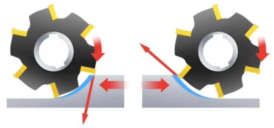
The first is climb milling, where the rotation direction of the milling cutter is the same as the feeding direction. The milling cutter grabs the workpiece and cuts the final chips at the beginning of the cut.
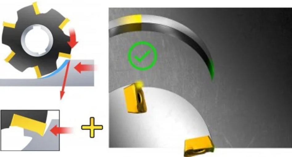
The second is conventional milling, where the rotation direction of the milling cutter is opposite to the feeding direction. The milling cutter must slide on the workpiece before starting the cut, starting with zero cutting thickness and reaching maximum cutting thickness at the end of the cut.
Milling Machining Methods
- Basic Milling: Includes plane milling, slot milling, side milling, and contour milling.
- Advanced Milling: Includes ramp milling, thread interpolation, trochoidal milling, push-pull contour milling, slotting, contour parallel milling, drilling.
Definition of Milling Machining Strategies
(1) Conventional Machining:
A strategy for general-purpose machining. The ratio of cutting width to cutting depth can vary depending on the type of operation.
- Tool Characteristics: Tools have relatively long cutting edges and small core diameters, with no high precision requirements.
- Machine Requirements: No special requirements.
- Application Areas: Basic CNC technology is available; advanced machining methods are not feasible; metal removal rates can only reach a moderate level; applications typically include small batch production and a wide range of materials.
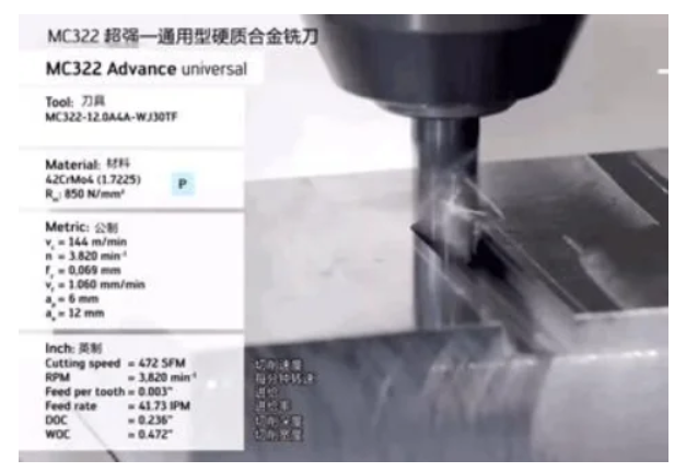
(2) High-Speed Machining:
A strategy that combines small radial cutting depths with high cutting and feed speeds; can achieve high material removal rates and low Ra values. Typical characteristics include low cutting forces, less heat transferred to the tool and workpiece, reduced burr formation, and high dimensional accuracy.
- Tool Characteristics: Stable (with a larger core diameter and shorter cutting length), clear and well-formed chip space, conducive to good chip evacuation, coatings.
- Machine Requirements: High-speed CNC control, high spindle speeds, fast table feed rates.
- Application Areas: Semi-finishing and finishing of hardened steels (48-62 HRC) in the mold industry, with short lead times. When used with the correct tools and advanced machining methods, this technique can also be applied to many other materials.
(3) High-Performance Machining:
A strategy that can achieve very high material removal rates. Typical characteristics include a cutting width of 1 times the cutter diameter and a cutting depth of 1 to 1.5 times the cutter diameter, depending on the workpiece material.
- Tool Characteristics: Special chip space structure developed on the tool’s chip groove, 45° tool tip, small plane or tool tip arc for protection, specially smooth chip space, coatings, with or without side clamping handle.
- Machine Requirements: High stability, high power requirements, high rigidity clamping system.
- Application Areas: Production efficiency is key in large-scale production machining, or for single-piece products with high metal removal rate requirements. (4) High-Feed Machining: A strategy that combines full-diameter cutting and small cutting depths with high feed rates. Can achieve high metal removal rates and good surface roughness.
- Tool Characteristics: Specially developed tool tips, extremely short cutting lengths, coatings.
- Machine Requirements: High stability, possibility of high feed rates.
- Application Areas: From soft steel to hardened steel, titanium alloys, and stainless steel, it is excellent as a pre-machining step before high-speed machining. It can also be used for deep cavity machining. One of the advantages of this technique is its ease of use for simple, safe, and fast programming in CAM. Using the so-called contour parallel milling strategy, it is easier to program complex shapes without extensive programming experience. (5) Micro Machining: A machining strategy using extremely small cutter diameters.
- Tool Characteristics: Diameter range from Ø0.1 to 2.0mm, short cutting length, wide range of outer circle diameter reductions, high precision, coatings.
- Machine Requirements: High spindle accuracy, high speeds, CNC, thermal stability to prevent spindle elongation.
- Application Areas: Various cavity machining on many types of materials.
Milling Summary
- Check the machine tool power and rigidity to ensure that the tool diameter used can have the shortest possible tool overhang on the machine tool.
- The number of teeth of the milling cutter is moderate to ensure that there is not too much tool engagement with the workpiece at the same time during machining to prevent vibration. Sufficient tool engagement with the workpiece is required when milling narrow workpieces or cavities.
- Appropriate feed per tooth to obtain good cutting effects when the chip thickness is thick enough to reduce tool wear. Use positive rake angle slot-type tool inserts for smooth cutting effects and minimum power consumption.
- Milling cutter diameter suitable for workpiece width.
- Correct primary clearance angle (45 degrees suitable for general milling).
- Proper milling cutter position.
- Use cutting fluid only when necessary; dry milling usually results in better tool life.
In the image above, without RTCP, the control system doesn’t account for tool length. The tool rotates around the axis center, causing the tool tip to shift from its original position.
In the second image, with RTCP enabled, the control system only changes the tool’s direction, keeping the tool tip in place. Necessary compensations on the X, Y, and Z axes are automatically calculated.
For five-axis machines and systems without RTCP, how do they handle linear axis coordinate shifts?
Many domestic five-axis machines and systems are considered “false five-axis” systems, meaning they lack RTCP functionality. The difference between true and false five-axis machines is not in appearance or whether five axes can move simultaneously—false five-axis machines can also achieve five-axis movement. The key difference lies in the lack of RTCP algorithms. In false five-axis systems, programming must account for the spindle length and the position of the rotary table. This means that CAM programming and post-processing must be carefully planned in advance.
With false five-axis systems, if the machine or tool changes, CAM programming and post-processing must be redone. Additionally, when clamping the workpiece, it must be precisely aligned with the rotary table’s center, which requires extra setup time and compromises accuracy. Even simple indexing operations can be more complicated with false five-axis machines. In contrast, true five-axis machines only need one coordinate system and one tool setup to complete the job.
False five-axis systems rely on post-processing to indicate the relationship between the 4th and 5th axis centers and compensate for the displacement of the linear axes caused by rotary axis movement. The resulting CNC program includes necessary X, Y, and Z compensation. However, this method leads to lower accuracy, reduced efficiency, and programs that aren’t reusable. Each machine requires a dedicated post-processor, which creates significant inconvenience in production.
Moreover, programs generated by false five-axis systems can’t be manually modified, making manual five-axis programming nearly impossible. Additionally, without RTCP, advanced five-axis features, such as five-axis tool compensation, cannot be used. In reality, a five-axis machine is just a tool to achieve a machining result, so there’s no true or false distinction. What’s important is that the selected process determines the machining method. True five-axis machines offer better value for money in the long run.
Contact us for expert support in custom machined parts. We’re dedicated to delivering high quality, precision, and quick turnaround for your projects.